Did some work.
Fusion was not exticing: various areas are not overlapped.
It ain't bad (1500-2), but I lack in alignement precision.
Do I have to work on scan quality (distorsion)? I guess wavyness is partially due to optical refraction of lights in wood. But misalignement here is an issue to be solved.
LG PF50, LG PF1500, RangeVision DIY: 2x DahengMer630, 2X12 and 2X16 mm 5Mp ZK lenses, RV turntable
3dxcan wrote: ↑17 Nov 2017, 05:34
Scan the calibration panel after calibration process and send me the stl file. I'll show you how much distortion you're having.
Hi
Can I know how can you measure distortion by scanning calib panel?
i use geomagic to determine the amount of deviation from plane you're getting on each side of the calibration panel.I call it the disortion map. thats a good indicator of the amount of distortion.
as an example this isnt a favourable:
Do you use also GOM inspect? I find it very powerful, fast and stable (and free).
If anybody in the forum is using it, I'll appreciate an indication of doing the same verification with GOM.
LG PF50, LG PF1500, RangeVision DIY: 2x DahengMer630, 2X12 and 2X16 mm 5Mp ZK lenses, RV turntable
mading wrote: ↑17 Nov 2017, 09:24
Hi to all, I gave a tried to GOM inspect 2016, free version:
I have to check the perpendicularity of my panel: it is measured as 90.05°:
90.05°.jpg
Then I can fit planes (easy and straighforward):
Clip_4.jpg
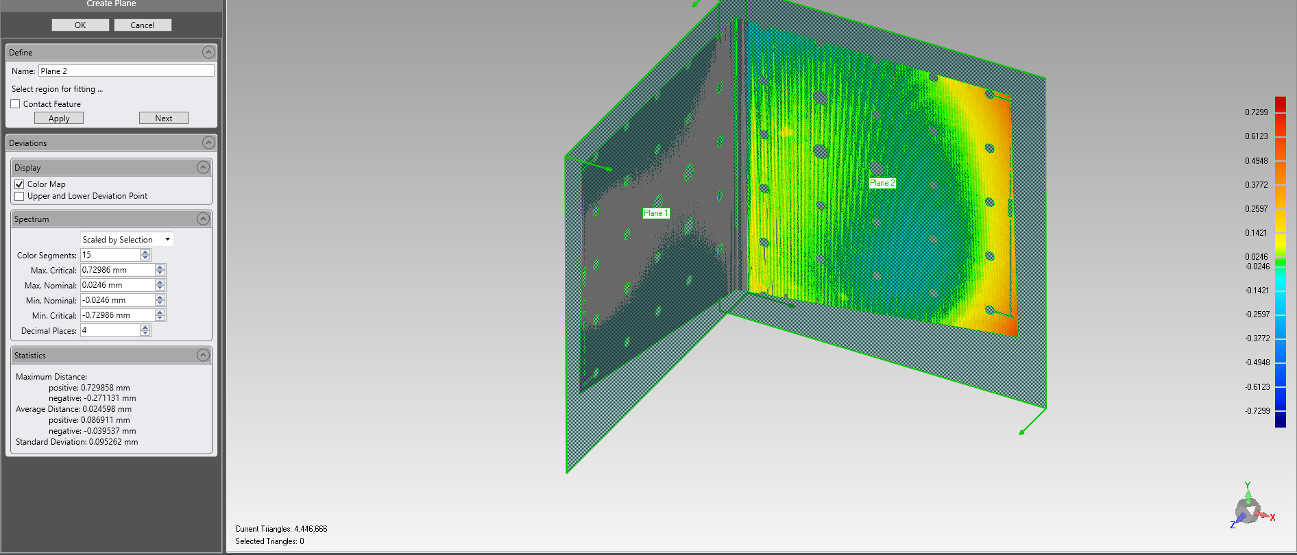
Here you have deviations from fitted planes:
Clip_2.jpg Clip.jpg
as you see in the pics, you have a center of yellow and green (~0.05 divation) which happens to be accelerating out of the divation zone (-0.15) as you move toward the calibration edges, gray areas on the corner are our of tolerance zone (-0.15,0.15).Its a lens problem. someone with a decent lens should give us his result.
what size of calibration panel are you using? whats the format of the camera sensor (eg 2/3", etc) and lens? what type of camera? global/rolling?
mading wrote: ↑17 Nov 2017, 08:20
Many thanks 3dxcan.
ASAP I'll send you the stl.
Do you use also GOM inspect? I find it very powerful, fast and stable (and free).
If anybody in the forum is using it, I'll appreciate an indication of doing the same verification with GOM.
by this method it is not defined the source of error (badly made calib panel or other sources). in all cases you may get the same deformation on mesh.