I just discovered this form, my first post here. I've multi-year experience with photogrammetry, but only recently purchased my first ever "proper" 3d scanner (Creality Ferret), and I am trying to come up with a good workflow for scanning.
I already had an Arduino operated turntable of my design, I just had to figure out how to automate the slow motion of the scanner over the object. Today I came up with this idea:
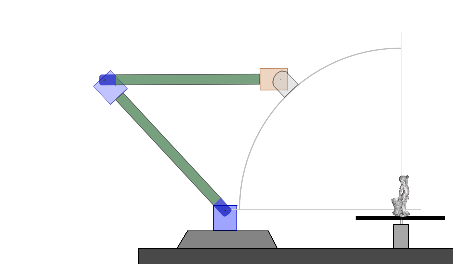
So it's basically a simplified robotic arm with three degrees of freedom (three servos). The two blue servos need to be more powerful - I ordered a couple of RDS3218 units with brackets (rated for 20 kg/cm - I think this should be sufficient). The orange servo can be a cheap SG-90 - it only has to turn the scanner itself (120g, very short distance from the servo). The three servos would be operated from an Arduino board (I'll write the code). Most of the parts (two arms etc) can be 3d printed.
As you can see, the constant distance from the scanned object (plus the scanner's pointing at the object) can be easily maintained. You just specify the distance to the Arduino code; it can be up to some largest possible value - this is the case shown in my diagram. Smaller distances are also possible (again, up to a point) - one just has to modify the angles for the three servos.
Sorry if a similar project is already discussed in this forum. I couldn't find anything recent on this topic.
Here is my estimate for the torque. The largest torque will be for the first blue servo (attached to the table). Assuming the weight of blue servos with brackets is m1 (0.1kg in my case), the weight of the 3d scanner head plus the small orange servo is m2 (~0.13kg for me), the weights of both arms (plastic parts connecting the servos) is the same - w (also assuming the arms are homogeneous - constant linear density), and the lengths for both arms is L, the torque for the bottom servo is
Q0 = L[cos(alpha)*(m1+m2+3*w/2)-m2-w/2].
Here alpha is the angle of the first arm relative to the table (goes from 0 to 90 degrees in my animation; can go up to 180 degrees if both arms are extended all the way to the right). I also assumed that the second arm is always horizontal (like in my animation) - this results in a circular orbit for the scanner. This assumption is not valid if we consider elliptic orbits. But the circular approximation is a good first order guess.
Special cases:
a) alpha=0 dgr: Q0 = L*(m1+w);
b) alpha=90 dgr: Q0 = -L*(m2+w/2);
c) alpha=180 dgr: Q0 = -L*(m1+2*m2+2*w);
Assuming m1, m2, and w have roughly the same value (~0.1kg), for circular orbits (alpha=0..90 dgr) Q0 doesn't go beyond 2*m*L in absolute value. If we allow both arms to extend to the right (alpha>90 dgr) - which we'd need if we want to scan a large flat object - then Q0 can go all the way to 5*m*L - 2.5 larger than in the circular case.
More specifically, with m1=0.1kg, m2=0.13kg, for alpha<90 dgr, and assuming w=0.1kg, my servo (rated at 20 kg*cm) can handle L up to 100 cm. Of course, a 1m arm will weigh much more than 0.1 kg. We can address this by assuming a constant linear arms density - say if a 20cm arm weighs 0.1kg, the linear density rho=0.1kg/20cm=0.005kg/cm. The worst case of alpha=0 becomes Q0=L*(m1+w)=L*(m1+L*rho). This now becomes a square equation for finding the largest possible L: L^2 * 0.005kg/cm + L * 0.1kg - 20kg*cm = 0. The only physical (positive) solution is: L=54cm. Meaning that the maximum length for each arm is 54cm. That's plenty! Of course the problem is to 3d print such a long arm. One can perhaps print it in segments, then join them together.
What if I am too optimistic with the arm's linear density of 0.005 kg/cm? For example, for twice denser arm (rho=0.01 kg/cm, corresponds to 200g per 20cm), solving the quadratic equation gives Lmax=40cm - still plenty, when scanning small objects at least.
For the second blue servo, the torque Q1 is easier to calculate. For the circular case (when the second arm is always parallel to the ground), Q1 is a constant: Q1=L*(m2 + w/2) = L*(m2 + L*rho/2). For the case described above (with L=54cm, m2=0.13kg, and rho=0.005kg/cm), Q2=14.3 kg*cm. As expected, Q1<Q0, and so is well within the servo's specs (20 kg*cm).
Finally, if we want a truly universal setup by allowing alpha>90 dgr, the largest torque situation is for alpha=180 dgr: Q0 = -L*(m1+2*m2+2*w). Plugging in my numbers (m1=0.1kg, m2=0.13kg, rho=0.005kg/cm), solving the quadratic equation gives L=30 cm. This will result in a smaller range for scanning, but should still be sufficient for Small size mode in Ferret scanner.
I don't know what your budget is, but these servos are very high torque, and have the drivers and encoders built into them. My partner has used them on very large 3D FDM printers, and they're phenomenal. Considering they are servos and you get the drivers and encoders with them, their prices are extremely reasonable. They would easily do what you want.